Reverse engineering machinery
My thoughts on the matter
This is something that is truly enjoyable to me, to take apart (fully, partially or even not at all) some interesting piece of machinery and to reverse engineer it as best as I can. Ultimately ending up with a fully functional set of designs, CAD drawings, notes, sketches; everything I’ll need to build the same machine from scratch. I don’t advocate doing this to copy machines, but there is a lot to learn by taking apart and thoroughly scrutinising a piece of equipment that has been professionally designed.

The machine to the right is designed to section food items into 8 equal sections. Melons, cabbages, etc.
It does this with 8 spinning circular blades, a set of 4 on the top and a set of 4 below. The product is conveyed by free fall, there is a guide to ensure the product stays centered until it passes part way through the final set of blades. Hence ensuring a centered (mostly) cut the whole way through.
Each blade has its own dedicated motor, contactor and no variable frequency drive. There are the standard token safety devices, inductive lid sensor, emergency stop buttons, phase monitoring relay, overloads. All in all, this machine is mechanically and electrically very simple. It took me half a work day to go from taking measurements to completing the drawings.
In the past, I would attempt to document the entire machine millimeter by millimeter, taking it fully apart and measuring every part exactly. That has proven itself to be a massive waste of time and honestly, boring. The better way in my opinion is to start with the critical mechanisms or components, size them up, then design from there a similar machine using the existing one as guidelines only.
My approach is always: do first. Too much planning bogs you down and you will never get it right the first time anyway. Start drawing and iterate from there, many details / problems will present themselves along the way and we solve these as they come.
The size of product that can be accommodated depends on the blade diameter. Do I want the same product dimensions? Yes. I take measurement of the blade diameter. Shaft diameter, not so interesting, but it is right there, easily measurable. I also measure the rotating speed of the blades with my tachometer, and then source for a suitable compact gear motor that I can purchase locally.
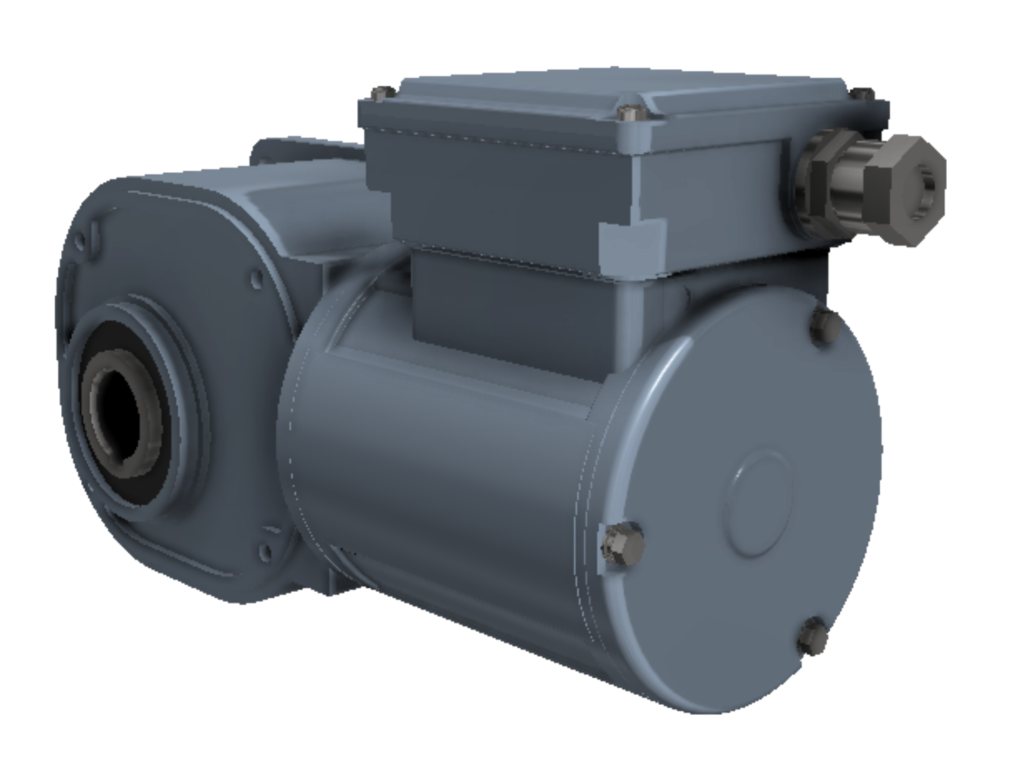
I obtain the motor CAD model, verify it with the manufacturer drawings. Make the blade model, create a suitable shaft that will couple to the motor and then set off to create the mounting frames!
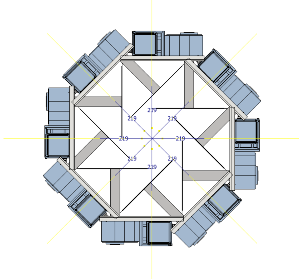
Since I know there are 8 sets of blades and motors, I’m dealing with a circular array with each element 45 degrees apart. The mounting frames consist of 4 top mounts and 4 bottom mounts. I start with only an array of one type of mount to first size up the frame length, shaft length, array center axis position, etc.
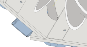
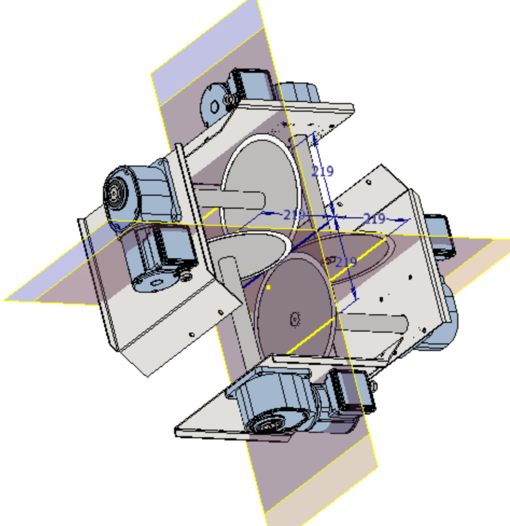
I set an arbitrary center position based on a rough measurement on the actual machine, then refine the frame design and length; creating a small 45 degree bent flange profile to enable each frame to overlap and couple onto the next one through 2 of the motor mounting holes. The exact hole placements will have to be dealt with later. The shafts also require a hole to emerge out of. Notice that the blades are all over the place, colliding with frames and other shafts. The shaft length is next on our chopping block.
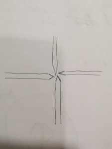
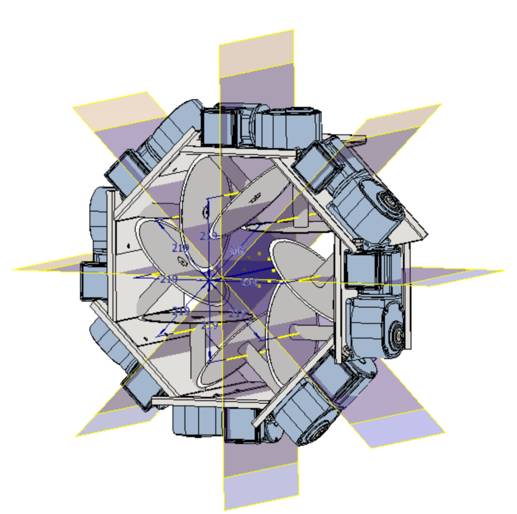
We want these blades to meet in the middle, with a healthy gap of 2mm and hopefully some lateral offset so that they can be closer while still not colliding. The cut does not need to go fully through, the product will spilt just fine as long as the middle gap is not too large.
Now I have the blades distanced just right. The next step is to remove every other array element because it is time to work on the second layer. The top layer is also not quite done as the overlapping flange hole placements need to be shifted down, shaft holes need to be added, etc. The next real design concern is having the bottom layer of blades close enough that the product is passed from blade set to blade set and not given enough empty space to re-orientate, this will create slanted cuts which we want to avoid. Obviously the second set of blades should not collide with anything as well.
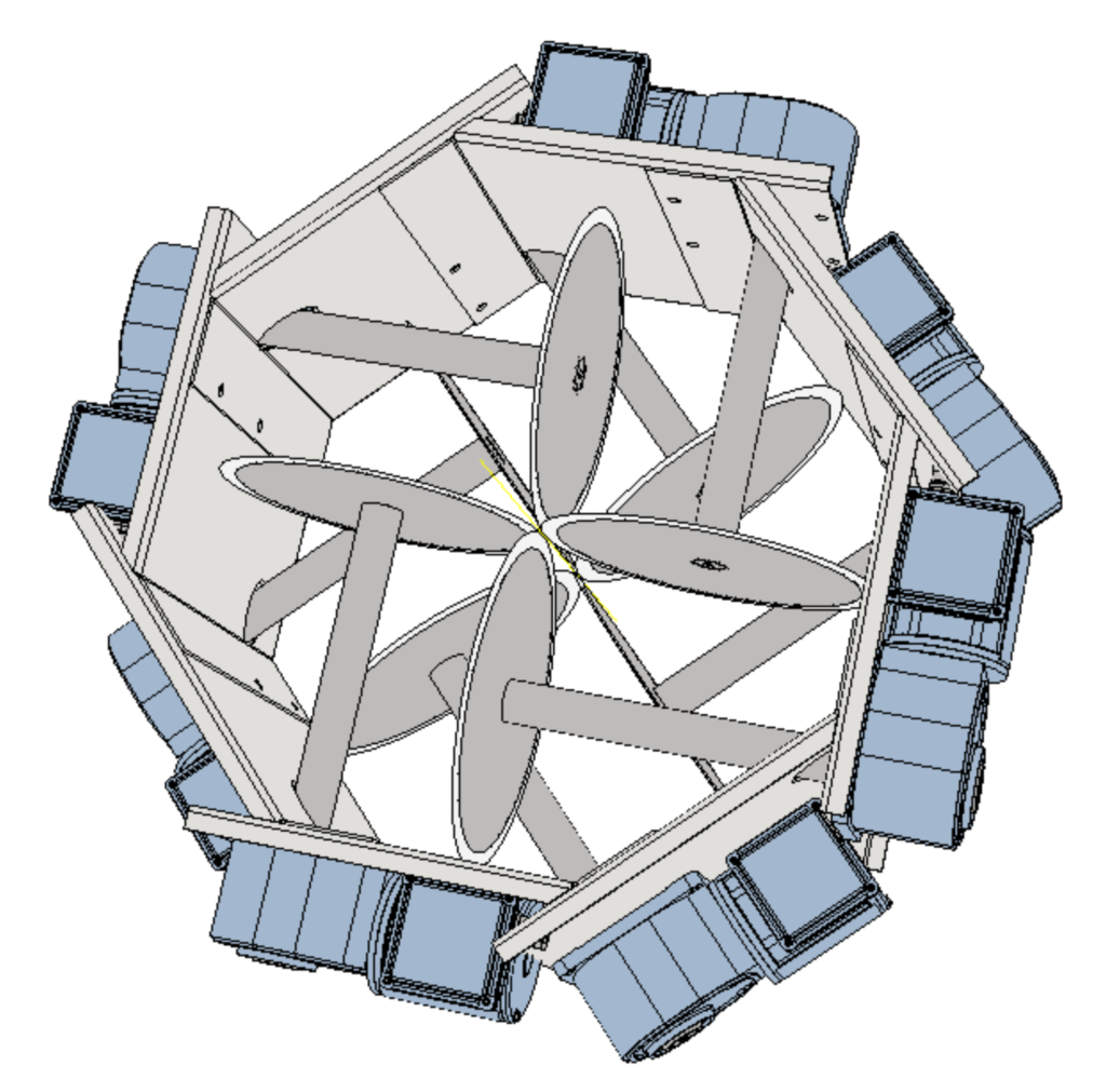
Aaand done. Added relevant cut outs for the frames not to intersect with the motors. The rest of it will just be sheet metal work and frame building. To house the main working mechanism and also to create a control box for housing the electrical components and control elements. Usually, I don’t complete the designs for the housing and peripheral bits. Those only really come into play when the machine is actually being built. You also want to take the space constraints into account or the feeding method, upstream/downstream equipment. Bla bla…
Also critical is the guiding tube for products so I have that modelled out as well. With that, I call it a day on this mini project.
The machine is more or less done. I can always revisit and upgrade the designs over and over as a form of practice / fun. For this sectioner, I’m thinking of reducing the number of motors. I can also follow the same concept to create different types of sectioning / cuts. There is the possibility to improve or automate the loading of products as well. Adding shaft sealing to improve waterproofing maybe.

“Kiss me, beneath the milky twilight
Lead me out on the moonlit floor”
— Sixpence None The Richer.